Insight Accelerator

CO2 Compression and Dehydration Technologies

  • Tools
3 Min Read Dec 19, 2025

In carbon capture, utilization, and storage (CCUS), compression and dehydration are two steps often used before transporting and storing captured carbon dioxide (CO2) underground. Compressing and dehydrating the CO2 is done to improve the efficiency of transportation and to meet the transport and storage operators’ specifications. Compression and dehydration systems are typically single train systems, meaning they consist of a single, non-redundant processing line. Since these systems lack redundancy, they need to be reliable.

  • Compressors are expensive, complex pieces of rotating equipment with large power requirements.  To ensure the compressor can operate optimally, a careful analysis of process parameters must be done. Improper selection can compromise process safety and reliability, leading to failures, costly maintenance, increased power consumption, and extended downtime.
  • Dehydration limits the risk of corrosion within pipelines and injection wells. Dehydration technologies for CO2 applications are well-established. However, depending on the required level of moisture removal required, operating expenses can be substantial.

There are multiple compression and dehydration technology options available. Explore the differences between technologies.

Where is Compression and Dehydration in the CCUS Value Chain?

  • For post combustion amine-based carbon capture, the CO2 captured from flue gas produces a low-pressure CO2 product stream. Compression increases the pressure of this stream, reducing its volume and converting the CO2 into dense phase. Dehydration reduces the water content within the CO2 product stream to meet the moisture limits set by the transportation and storage operators. Dehydration is crucial for preventing pipeline corrosion and hydrate formation.

  • CO2 compression is typically achieved through transcritical compression, where low pressure gaseous CO2 is compressed in multiple stages to reach supercritical conditions, and then cooled to dense phase conditions suitable for pipeline transportation. Compression is divided into two sections -wet and dry- separated by a dehydration unit.

    Six stages of compression (four wet stages and two dry stages) are shown; however, it is common to see a total of eight stages (four wet and four dry) in industry. The number of stages is dependent on the inlet pressure of the compressor and the final transportation pressure required.


    1. Wet Section: CO2 is compressed in multiple stages to reach optimal conditions for dehydration. Each stage of compression is followed by an intercooler and knockout drum to remove condensate and help the stream achieve an ideal temperature for the next stage of compression.
    2. Dehydration Unit: Water is removed from the CO2 product stream to meet pipeline and storage specifications. The dehydration unit is typically placed at an intermediate point of the compression train for ideal moisture removal and to ensure economic design pressures.
    3. Dry Section: CO2 is compressed to its final pressure and then cooled to temperatures required for meeting the CO2 product specification for the transportation and storage operator(s).

CO2 Compression Technologies

Compare the various compressor technologies for CCUS applications below.

  • Single-shaft centrifugal compressor

    How it works: Features multiple impellers arranged on a single rotating shaft, increasing gas pressure by accelerating the fluid through each stage in series.

    Technology Application: This design allows for higher pressure ratios to be achieved within a compact unit.

    See details
  • Integrally geared centrifugal (IGC) compressor

    How it works: Utilizes a large single bull gear to drive multiple pinions, each connected to an individual impeller operating at its optimal speed.

    Technology Application: This design allows for independent speed control of different compression stages, leading to higher efficiency and specialized pressure ratios in a compact footprint.

    See details
  • Reciprocating compressor

    How it works: Employs multiple cylinders in series, where pistons move back and forth to sequentially compress gas to increasingly higher pressures.

    Technology Application: This design is highly effective for achieving very high-pressure ratios and handling a wide range of gas types, making it robust for demanding industrial applications.

    See details

Capacity is key when selecting a compressor technology. Larger scale capture facilities (over ~1 million tonnes of CO2 per year) can’t typically use reciprocating compressors as multiple would be required which increases capital costs. Selecting a single shaft or an integrally geared compressor isn’t as straight-forward. There are many factors that can influence the project owner’s decision such as:

  1. Capital Cost: Project owners continually assess overall cost as a key factor for major equipment purchases.
  2. Industry Experience: Most project owners do not own and operate large CO2 compressors. Instead, they tend to rely on proven experience, using specific CCUS deployments and references from other owners operating in the same environment.
  3. Efficiency: CO2 compressors are large, complex, and energy intensive.  Power requirements and performance characteristics determine their operational efficiency.
  4. Reliability and Maintainability: Failures and downtime impacts maintenance costs and availability of equipment.
  5. Owner’s Experience: Some project owners may lean towards a particular type of compressor based on their own operating experience and commonality amongst their rotating assets.

Integrally geared centrifugal compressors are selected the most often for CCUS applications. This is due to their early and proven adoption in CCUS applications, their relatively small footprint, and highest overall efficiency when compared to the other compressors.

Compare CCUS Technologies

Technologies Single-shaft centrifugal compressor Integrally geared centrifugal (IGC) compressor Reciprocating compressor
Image
Maturity

TRL 9 – Commercially proven.

Well established technology used in several industries such as oil production, refineries, fertilizer plants, etc.

TRL 9 – Commercially proven.

Mature and reliable technology with notable applications in CCUS.

TRL 9 – Commercially proven.

Mature and reliable technology used in hydrogen production and Enhanced Oil Recovery (EOR) using CO2.

Configuration

Typically includes two units (low-pressure and high-pressure section) which are interconnected by a speed increaser (gearbox)

Single unit can incorporate all compression

Typically includes multiple units (which are volume dependent) with separate drivers

Capacity, m3/h

Up to 800,000

Up to 500,000

Up to 100,000

Overall Efficiency, %

Higher

Highest

High

Pressure ratio per stage

1.1-1.7

2.5

1.3-3

Maximum Discharge Pressure, bar

Up to 500

Up to 250

Up to 800

Reliability, %

> 99

> 99

95 – 97

Turndown Ratio

1.25:1

1.25:1

5:1

Footprint (assuming equivalent capacities between compressors)

Larger footprint than integrally geared centrifugal compressors, but allows for a compact layout.

Smaller footprint in comparison to single-shaft centrifugal compressor and reciproctating compressors. Intercooler is arranged below the compressor and no separate speed increaser is necessary.

Larger footprint than integrally geared centrifugal compressors and single-shaft centrifugal compressors, as a multiple compressor train is required and does not allow a compact layout

Interval Between Overhaul, yrs

~ 5

~ 5

~ 3

Maintenance Duration

Medium

High

Low

Maintenance Accessibility

Relatively easy to maintain

Complex due to multiple stages and gearing

Easier to repair

Risk for CCUS application

Technology is widely adopted in other industries, but has minimal applications in operating CCUS facilities

Technology is widely adopted, with many successful installations in operating CCUS facilities

Technology is widely adopted, with proven CO2 applications at smaller scales. Increased risk when compared to single shaft centrifugal compressor due to a larger amounts of moving parts.

Power Consumption

10-20% higher than integrally geared centrifugal compressors

10-15 MW

5-10% higher than integrally geared centrifugal compressors

CO2 Dehydration Technologies

Dehydration systems remove water from a CO2 product stream to achieve the desired levels of dryness to meet pipeline and storage specifications.  Factors such as the phase in which CO2 is being transported, and the concentration of other impurities present in the stream influence the product’s water limitations.

Compare the various dehydration technologies with a proven track record in CCUS applications below.

  • Absorption Dehydration using Triethylene glycol (TEG)

    How it works: In the absorber, the water from the wet CO2 product stream is dissolved into a liquid solvent (i.e., liquid triethylene glycol (TEG)), removing it from the CO2 product stream and yielding dry CO2.  The rich TEG (water and TEG) is heated and sent to a regenerator, where the water is boiled off and the lean TEG is recirculated back to the absorber for reuse. 

    Technology Application: Removal of water from gas streams to approximately 50 ppm.

    See details
  • Adsorption Dehydration using Activated Alumina

    How it works: This uses a cyclic process known as pressure swing adsorption (PSA). The wet CO2 product stream flows through one vessel containing a solid desiccant (i.e., molecular sieve, silica gel, or activated alumina) where the water molecules physically bind to the desiccant surface (adsorption), removing it from the CO2 product stream and yielding dry CO2.  Once saturated, the wet desiccant in the same vessel is regenerated (desorption) using recycled dry CO2 that is heated, while the other vessel initiates the adsorption process. Typical PSA units have multiple two-vessel arrangements to accommodate the required flowrates.

    The different desiccants used in the adsorption process have unique properties which dictate their ability to remove water.

    Technology Application: Removal of water from gas streams to 10 ppm and below.

    See details
  • Adsorption Dehydration using Silica Gel

    How it works: This uses a cyclic process known as pressure swing adsorption (PSA). The wet CO2 product stream flows through one vessel containing a solid desiccant (i.e., molecular sieve, silica gel, or activated alumina) where the water molecules physically bind to the desiccant surface (adsorption), removing it from the CO2 product stream and yielding dry CO2.  Once saturated, the wet desiccant in the same vessel is regenerated (desorption) using recycled dry CO2 that is heated, while the other vessel initiates the adsorption process. Typical PSA units have multiple two-vessel arrangements to accommodate the required flowrates.

    The different desiccants used in the adsorption process have unique properties which dictate their ability to remove water.

    Technology Application: Removal of water from gas streams to 10 ppm and below.

    See details
  • Adsorption Dehydration using Molecular Sieve 4A

    How it works: This uses a cyclic process known as pressure swing adsorption (PSA). The wet CO2 product stream flows through one vessel containing a solid desiccant (i.e., molecular sieve, silica gel, or activated alumina) where the water molecules physically bind to the desiccant surface (adsorption), removing it from the CO2 product stream and yielding dry CO2.  Once saturated, the wet desiccant in the same vessel is regenerated (desorption) using recycled dry CO2 that is heated, while the other vessel initiates the adsorption process. Typical PSA units have multiple two-vessel arrangements to accommodate the required flowrates.

    The different desiccants used in the adsorption process have unique properties which dictate their ability to remove water.

    Technology Application: Removal of water from gas streams to 10 ppm and below.

    See details

The main factors to consider when selecting a dehydration technology are the desired moisture level and operating costs. As the desired moisture level is primarily dictated by the transportation and storage operator, the project developer may be limited on their options. With higher allowances for moisture levels, absorption is typically selected and with stringent moisture levels, adsorption technologies are typically selected.   

The most commonly selected dehydration technology for CCUS applications is absorption, using triethylene glycol (TEG) as the liquid solvent. Current CCUS projects are using TEG dehydration mainly because it is a proven technology that meets or exceeds pipeline moisture specifications, and it has a lower capital and operating cost when compared to adsorption.   

Compare CCUS Technologies

Technologies Absorption Dehydration using Triethylene glycol (TEG) Adsorption Dehydration using Activated Alumina Adsorption Dehydration using Silica Gel Adsorption Dehydration using Molecular Sieve 4A
Image
Maturity

TRL 9 – Commercially proven

TRL 9 – Commercially proven

TRL 9 – Commercially proven

TRL 9 – Commercially proven

Operability

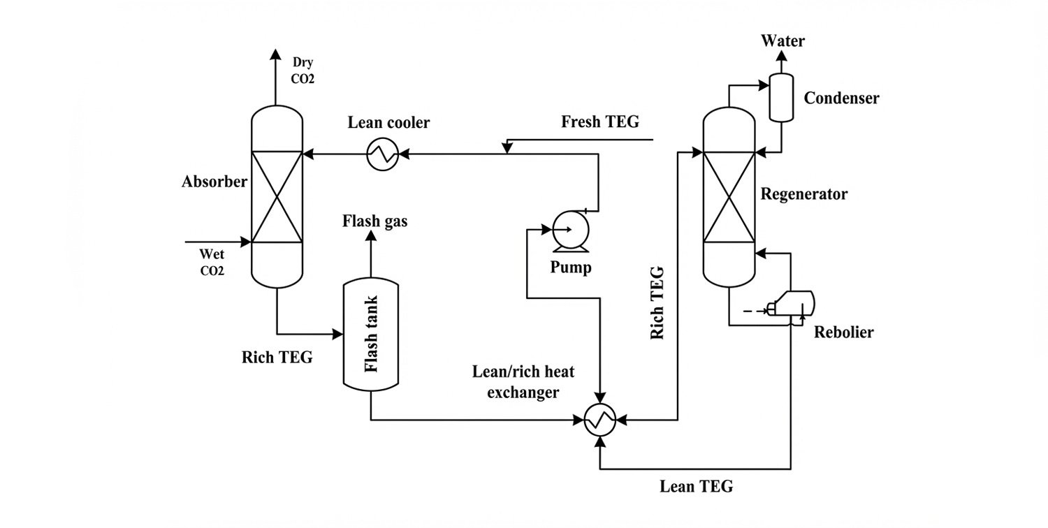
Continuous operation, requiring TEG makeup.

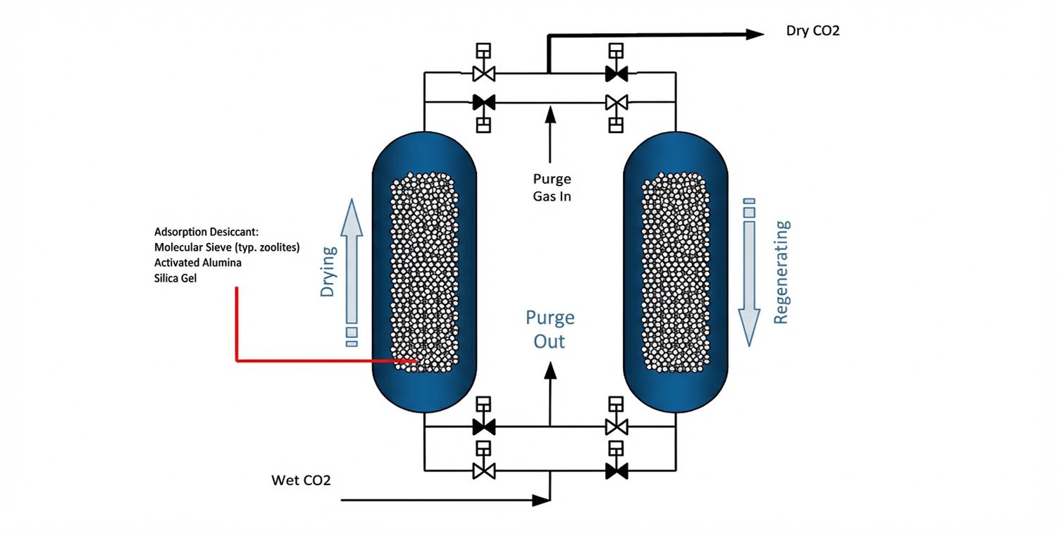
The desiccant has a two-year lifespan.

The desiccant has a five-year lifespan.

The desiccant has a three to four year lifespan.

Desiccant Shape & Sizes

N/A

Spherical

Sizes available include: 14 mesh, 3mm, 5mm, 6mm

Spherical

Sizes available include: 8 mesh, 2mm

Pellets (extruded cylinders or spherical)

Sizes available include: 1.6mm, 3.2mm, 6mm dia. cylinders

Desiccant Surface Area, m2/g

N/A

325-360

650-750

600-800

Regeneration Temperature, °C

190-204

150-200

100-120

200-300

Regeneration Frequency

Continuous

High

Moderate

Low

Operating Pressure, barg

Up to 64.5

Capable of withstanding higher pressures than adsoprtion dehydration using TEG

Capable of withstanding higher pressures than adsoprtion dehydration using TEG

Capable of withstanding higher pressures than adsoprtion dehydration using TEG

Turndown Ratio

10:1

10:3

10:3

10:3

CAPEX

$

$$

$$

$$

OPEX

$

$$

$$$

$$$$

Achievable Water Content, ppm mol

50

10

10

1

Footprint

Smaller footprint compared to adsorption dehydration technologies

Larger footprint than absorption dehydration technology using TEG

Larger footprint than absorption dehydration technology using TEG

Larger footprint than absorption dehydration technology using TEG

Risks

– TEG carryover with the CO2 product
– TEG losses with absorbed water during regeneration
– Risk of degradation of TEG in the presence of O2.

– Sensitive to acidic impurities (SOx, NOx, H2S) so at risk of deactivation and increased replacement rate.
– Risk of clogging if particulates are present in the CO2 product.

‘- Risk of clogging due to sulphur deposition in the presence of H2S. H2S content should be kept below 5%.
– Risk of deactivation by alkaline content (NH3, caustic)

– Risk of molecular sieve binder breakdown in the presence of caustic and acidic impurities, forming dust.
– Risk of plugging due to elemental sulfur and higher hydrocarbons in the presence of O2.

The CCUS Insight Accelerator (CCUSIA) is a partnership between the Government of Alberta and the International CCS Knowledge Centre to accelerate and de-risk CCUS by sharing knowledge and developing insights from projects.