Breakdown of Carbon Dioxide, Methane and Nitrous Oxide Emissions by Sector
Ritchie, H.; Rosado, P.; Roser, M.
Carbon capture, utilization and storage (CCUS) is one of the only proven solutions available to reduce carbon dioxide (CO2) emissions from industries such as power, cement, oil and gas, and iron and steel. However, this is more complicated than just adding a carbon capture unit to an existing facility.
Each industry has different CO2 emissions sources with varying CO2 concentrations, which impacts the efficiency and cost-effectiveness of carbon capture. There are also unique challenges faced by each industry when implementing CCUS, which can impact carbon capture performance. To illustrate the complexities of carbon capture, this piece highlights CO2 emission sources, unique challenges, and decarbonization strategies for the power, cement, oil & gas, and iron & steel industries.
Power plants generate electricity by either burning fossil fuels (e.g. coal, natural gas, oil, etc.) or by using clean energy sources (e.g. hydropower, nuclear power, solar, wind, etc.). The majority of global power generation comes from burning coal and natural gas, and therefore most emissions come from coal-fired power plants and natural gas-fired combined cycle power plants.
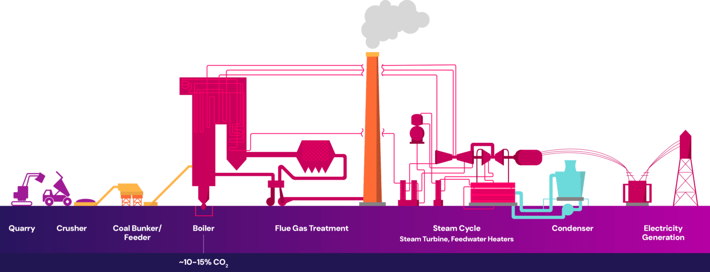
In coal-fired power plants, coal is burned in a boiler to generate heat. This heat produces steam which is used to spin a turbine and generate electricity. The combustion of coal in the boiler is a key component in generating electricity and is the primary source of CO2 emissions in the process. The single point source emissions are then released out of the flue gas stack, as shown below.
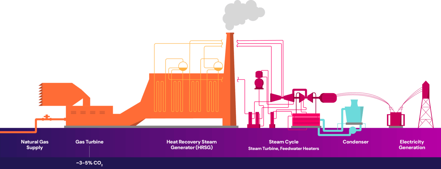
In natural gas-fired combined cycle power plants, natural gas is burned in a gas turbine to generate electricity. The hot exhaust gases from this process are then used to produce steam, which drives a steam turbine to generate additional electricity. The combustion of natural gas is a key component in generating electricity and is the primary source of CO2 emissions in the process. The single point source emissions are then released out of the flue gas stack, as shown below.
The impurities present in the flue gas vary between coal-fired power plants and natural gas-fired combined cycle power plants. Flue gas from coal-fired power plants contains impurities such as sulfur oxides, nitrogen oxides and particulates – primarily from fly ash. When more impurities are present, more pre-treatment or purification of the flue gas is needed, which can lead to higher energy consumption, increased operational complexity, and increased costs.
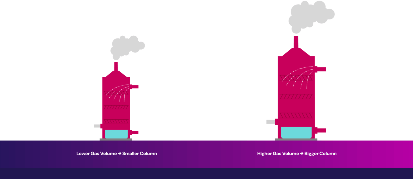
In contrast, natural gas power plants produce cleaner flue gas with fewer impurities like sulfur oxides and particulates. Because the flue gas is cleaner, the pre-treatment requirements are reduced, and maintenance demands are lower. However, the flue gas has a lower CO2 concentration, making carbon capture more energy-intensive due to the need to separate CO2 from a more dilute stream. Additionally, larger equipment is needed to handle the increased gas volume to capture the same amount of CO2, contributing to higher capital costs.
Some power generation fluctuates – increasing or decreasing electricity output as needed, depending on the demand from consumers. This creates added complexity for carbon capture. When these fluctuations are significant and frequent, they can disrupt the steady-state conditions that carbon capture systems typically perform best at, reducing their efficiency and reliability.
There are two main strategies the power industry is pursuing to mitigate emissions: capturing CO2 from point source emissions before they are released into the atmosphere and transitioning to low-carbon fuel sources such as hydrogen, biofuels, or other bio-based feedstocks.
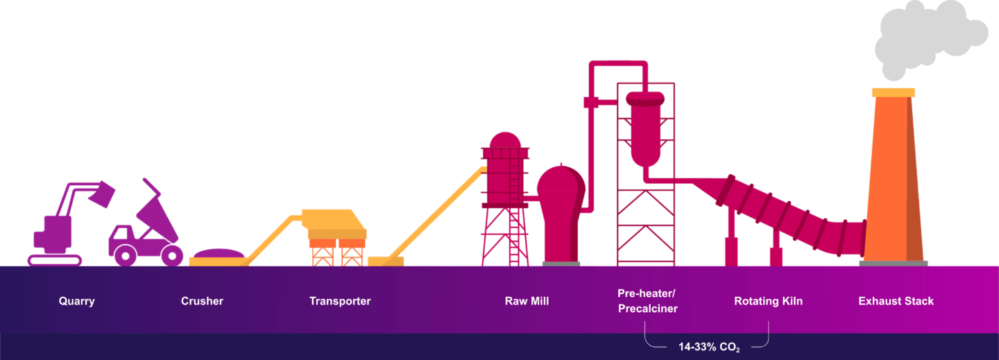
Cement production is considered a hard-to-abate industry due to the reliance on fossil fuels, and the emissions created from the high temperature chemical reactions required to make clinker, a key component in cement that allows cement to harden when mixed with water to create concrete.
Cement production involves crushing and blending raw materials (e.g. limestone, clay, etc.) and subjecting them to high temperatures in the kiln to form clinker. The calcination of limestone is essential for creating clinker. The transformation happens at temperatures above 1,400 degrees Celsius and creates most of the CO2 emissions, with the remainder of emissions coming from the combustion of fuel to heat the kiln. Single point source emissions come from the exhaust stack of the cement kiln, as shown below.
Cement flue gas contains various contaminants originating from the raw materials used in clinker production and the combustion of fuels to heat the kiln. This introduces impurities to the flue gas such as sulfur oxides, nitrogen oxides, particulate matter and trace metals. While pre-treatment technologies can effectively remove many of these impurities, small amounts can still bypass the equipment, impacting the performance of the carbon capture system.
Another unique challenge when implementing CCS with cement production is the composition of flue gas can fluctuate based upon factors like raw mill operation and the use of alternative fuels to reduce emissions. Raw mill operation within the cement process consists of grinding and feeding raw materials such as limestone into the kiln for clinker production. This influences the flue gas temperature and may affect the concentration of some components in the flue gas, impacting carbon capture performance. The increasing use of alternative fuels (to replace a portion of a more carbon intensive fuel) to heat the kiln introduces changes in flue gas chemistry, as the composition of these fuels can vary widely. Although this benefits the environment by reducing emissions, it increases the operational complexity and performance of the capture facility.
To reduce emissions from fuel combustion to heat the kiln, decarbonization efforts include switching to lower carbon intensive fuels. However, this only reduces a portion of CO2 emissions, as a significant amount of CO2 is generated from the chemical reactions in clinker production which cannot be similarly eliminated. Strategies to reduce the CO2 generated in clinker production include reducing the clinker to cement ratio and integrating carbon capture into the manufacturing process.
The oil and gas industry has three main sectors: upstream (exploration and production), midstream (transportation and storage terminals) and downstream (refineries and distribution). This discussion will focus on upstream and downstream oil sands operations as they are the most emissions intensive.
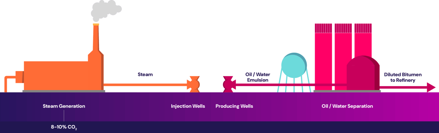
Steam-assisted gravity drainage (SAGD) is a recovery method used to access the majority of the Canadian oil sands deposits that are too deep to mine.
The SAGD process requires high-pressure, high-temperature steam to be injected several hundreds of meters underground to heat the heavy bitumen, allowing it to flow to surface through a production well. The primary source of CO2 emissions comes from burning natural gas in the steam generators to produce steam. The point source emissions are then released out of the steam generator’s flue gas stack, as shown below.
Similar to natural gas power plants, the flue gas coming out of the steam generators is relatively clean with fewer impurities. However, the flue gas has relatively low CO2 concentration, and separating out the CO2 from a more dilute stream is more energy intensive, contributing to higher operating costs. Additionally, larger equipment is needed to handle the increased gas volume to capture the same amount of CO2, contributing to higher capital costs.
In addition, steam generators may have individual flue gas composition depending on the site’s configuration. When the flue gas from multiple steam generators are combined before entering the capture plant, the differences in individual flue gas compositions can impact capture performance.
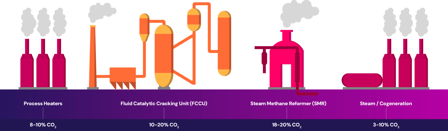
Oil refineries use a series of processes to convert crude oil into finished petroleum products (e.g., gasoline, diesel, jet fuels, etc.).
Oil refineries have multiple emission sources throughout the operations. At a refinery, emissions are generated from the combustion of fuel in process heaters which heat the crude oil for processing. The fluid catalytic cracking unit (FCCU) converts heavy hydrocarbons into lighter hydrocarbons, generating emissions from the chemical reactions. The production of hydrogen from the steam methane reformers (SMR) produces emissions through the combustion of fuel to supply heat and from the chemical reaction that takes place in the reforming process itself. The refinery also creates emissions from power and steam generation. The emissions are released at each source throughout the process, as shown below.
Each refinery has its own configuration of the processes outlined here, making the industry unique compared to other heavy emitting industries. Each facility is typically designed to take specific feedstock(s) and produce a particular range of products. This diversity in design leads to differences in emissions profiles and influences the options available for emissions reduction.
Unique challenges for refineries when implementing CCS include:
The oil and gas industry is decarbonizing its operations with the integration of CCUS, enhancing energy efficiency, electrification, reducing methane emissions, switching to low-carbon fuels, digitization, and integrating renewable energy solutions.
Iron and steel production is an energy-intensive process which produces steel from rocks and minerals called iron ore, which metallic iron can be extracted from. It has historically relied heavily on the use of coal as a fuel to generate the high temperatures needed in the process. The coal also produces coke which is used in the steelmaking process to reduce iron ore into iron.
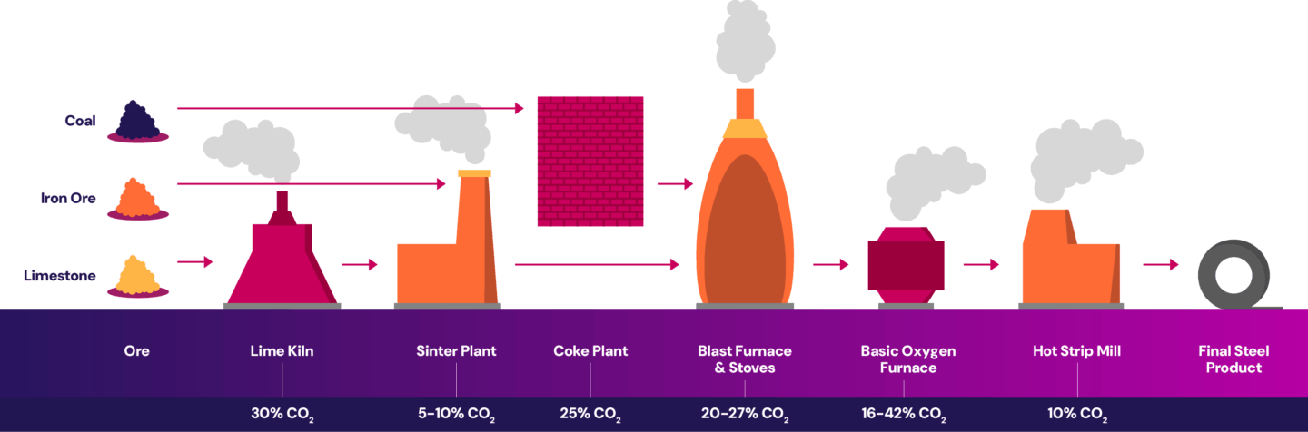
The iron and steel industry has various emission sources at each stage of the process. The ironmaking process generates emissions during the calcination of limestone. The lime kiln is heated by combusting fuel. The lime, iron ore and coke are processed and sent to the sinter plant where they’re ignited by burning fuels. The coke plant burns fuel to heat coal and produce coke. In the blast furnace, iron oxides (from the iron ore) are reduced into crude iron creating emissions.
The steelmaking process generates emissions from the refining of crude iron in the basic oxygen furnace to produce molten steel and eventually slabs. Emissions are also created from combusting fuel for the reheat furnace in the hot strip mill to reheat the slab before it’s rolled into a final product. Emissions are released at each point in the process, as shown below.
The iron and steel industry have several emission points with unique CO2 concentrations. Like refineries, carbon capture projects at iron and steel facilities must evaluate the feasibility of integrating multiple capture points or combining flue gas streams, impacting design, overall costs and adding operational complexity. If carbon capture is applied only to select emission sources, there may be only a modest reduction of the site’s overall emissions.
In addition, the flue gas from each point source has a unique composition. Flue gas impurities are abundant in this industry due to the inherent nature of the materials and the reactions involved in processing them. As a result, they can vary significantly across the different emission points. Pre-treatment requirements will vary depending on the impurities present and can add significant capital costs to the project. Pre-treatment also won’t completely eliminate all risks of carrying over impurities to the capture facility.
Because of these challenges, decarbonizing with capture may not be the best way to reduce emissions in all scenarios. The number of capture projects on traditional steel mills has stalled, with hydrogen-based projects gaining more momentum. Technologies such as hydrogen-based direct reduction of iron ore, is currently being developed and deployed globally at scale. This process uses green hydrogen gas (produced from the electrolysis of water) to reduce iron ore into fossil-free metallic iron, then an electric arc furnace (EAF) is used to produce crude steel.
Ritchie, H.; Rosado, P.; Roser, M.
2024; accessed 2025-06-15.
International Energy Agency; 2025.
Khaiyum, M. Z.; Sarker, S.; Kabir, G.; Sustainability (Switzerland) 2023, 15 (21).
International Energy Agency; 2018.
International Energy Agency; 2023.
COSIA; 2022
2022; accessed 2025-06-11.
International Journal of Greenhouse Gas Control 2024, 135.
Zuberi, M. J. S.; Shehabi, A.; Rao, P.
2024; accessed 2025-02-08.
2024; accessed 2025-06-12.
In Journal of Physics: Conference Series; Institute of Physics Publishing, 2017; Vol. 914.
Selamat, S. N.; Nor, N. H. M.; Rashid, M. H. A.; Ahmad, M. F.; Mohamad, F.; Ismail, A. E.; Hassan, M. F.; Turan, F. M.; Mohd Zain, M. Z.; Bakar, E. A.; Seiji, Y.