Insight Accelerator

Cryogenic Carbon Capture Technology Overview

  • Resources
8 Min Read Jan 27, 2026

Why is cryogenic carbon capture gaining attention now?

As we look to meet our climate goals and reduce the costs of CCUS, there has been growing momentum to advance carbon capture technologies beyond traditional amine-based systems. Cryogenic carbon capture is among the emerging solutions, with two methods currently at different stages of development. Cryogenic desublimation has progressed to a technology readiness level (TRL) of 5-6, while cryogenic distillation is more mature, with a TRL of 6-9 (learn more about TRL’s here). Even at different readiness levels, both methods have demonstrated success in laboratory and small-scale deployments.

Cryogenic carbon capture stands out for its ability to process high CO2 concentrations. Cryogenic capture can also achieve high CO2 recovery rates and operates without the need for thermal energy consumption (i.e., steam). The technology is applicable to a wide range of heavy industries, including steam-methane reforming, cement and lime production, iron and steel manufacturing, oil refineries, pulp and paper mills, and power plants.1 Additionally, this technology can be applied to both pre- and post-combustion flue gases, making it a versatile option for carbon capture projects.


What is cryogenic carbon capture?

To separate the CO2 from flue gases, cryogenic carbon capture uses low temperatures (e.g., temperatures can be as low as -50ºC). The technology is based on the principle that different gases condense or solidify at different temperatures, enabling selective CO2 removal through controlled cooling.

There are two main methods:

  • Cryogenic distillation: This method cools gas streams to liquefy and separate the CO2. Click here to understand how cryogenic distillation is applied in post-combustion applications.
  • Cryogenic desublimation: This method freezes CO2 directly into a solid (i.e., dry ice), skipping the liquid phase entirely. Click here to understand how cryogenic desublimation is applied in post-combustion applications.

Want to understand the advantages and limitations of each cryogenic method? Explore our CCUS Technology Comparison Guide to help select the appropriate capture technology for your project’s specific needs.


Cryogenic Distillation for Post-Combustion Carbon Capture

The cryogenic distillation process begins with cleaning and cooling the flue gas to remove particles, moisture, and contaminants before the gas is compressed and dehydrated. From there, a pressure swing adsorption (PSA), as shown below, or membrane system is used to increase the CO2 concentration in the flue gas stream before it enters the cryogenic stage. This concentration step is essential, as cryogenic separation is most energy-efficient when CO2 concentrations exceed 50%.2 Once concentrated, the flue gas enters the cryogenic system where it undergoes pre-cooling, liquefaction, separation, and distillation. The resulting high-purity liquid CO2 can then be reheated into a gas and compressed to high pressures for pipeline transport, or kept in the liquid phase if being transported via ship, rail, or truck.3  


Cryogenic distillation process

  • Pre-treatment cleans the flue gas stream by removing particles and other contaminants before entering downstream processes. If acidic components like hydrogen sulfide (H2S) or sulfur dioxide (SO2) are present, pre-treatment plays an important role in removing these contaminants, preventing corrosion and damage to downstream equipment. The Direct Contact Cooler (DCC) further cools the gas, condensing water and helping to scrub out any remaining particulates carried with the flow. This step also reduces the load on subsequent systems like dehydration and refrigeration, as it lowers the overall volumetric flow.


  • The flue gas compressor increases the pressure of the gas from near atmospheric levels to a range suitable for downstream processes like dehydration and PSA. Compression typically occurs in multiple stages, with intercoolers between stages to manage gas temperatures, and improve the system’s energy efficiency. Knock-out drums are also integrated between stages to remove any condensed liquids that form during compression.


  • Dehydration removes moisture from the flue gas stream, preventing operational issues in downstream equipment such as PSA units and cryogenic systems. This is typically achieved using molecular sieves or activated alumina, which reduce water content to parts-per-million (ppm) levels. Moisture removal is critical because water can freeze under cryogenic conditions, forming ice or hydrates that may block equipment and disrupt operations. Additionally, excess moisture can degrade adsorbent materials in PSA units, reducing their efficiency and lifespan.


  • PSA increases the CO2 concentration in a flue gas stream. This process selectively absorbs non-condensable gases such as nitrogen (N2) and oxygen (O2) onto a solid adsorbent material under high pressure. When the pressure is reduced, these adsorbed gases are released and vented to atmosphere, leaving behind a gas stream enriched in CO2. This concentrated CO2 stream is then fed into the cryogenic separation system for further purification as the PSA cannot remove 100% of the non-condensable gases.


  • The medium pressure compressor increases the pressure of the CO2-rich gas to meet the requirements of the next stage, cryogenic distillation. This is usually done through multi-stage compression with intercooling, which helps manage temperatures and improves the system’s energy efficiency. Since the gas has already been dehydrated upstream to ppm-level moisture content, there’s minimal risk of water condensation during compression. As a result, knock-out drums for condensate removal are generally not required in this stage.


  • After the pressure is increased, the flue gas stream first enters a pre-cooler, where it is cooled by returning cold streams from other processes. It then flows into a liquefier, where the refrigeration system further reduces the temperature to cryogenic levels, initiating the condensation of CO2. Next, the partially condensed stream enters a separator, which separates the liquid CO2 from the remaining cold gas. The cold gas exiting the top of the separator is routed to the condenser, where it provides additional cooling to support the distillation process. The liquid CO2 is fed into a distillation column, where further purification occurs. At these ultra-low temperatures, CO2 remains in the liquid phase, while lighter gases such as nitrogen and oxygen stay in the gas phase and are vented from the system. This setup ensures high-purity CO2 recovery through phase separation and temperature control. The condensed liquid CO2 is collected at the bottom of the column and transferred to the next process.


  • When CO2 is intended for pipeline transport, a heater or vaporizer is used to convert liquid CO2 into its gaseous form before compression and pipeline delivery. Since pipelines are typically designed to transport CO2 in a supercritical gas phase, the heater ensures complete vaporization of the CO2 stream. However, if CO2 is being transported via ship, rail, or truck, it is often stored and moved in its liquid form, and this vaporization step and the high-pressure compressor may not be necessary.


  • The high pressure compressor compresses gaseous CO2 to pressures required for pipeline transport, which vary depending on pipeline specifications. A multi-stage compression system with intercooling is commonly used to manage temperatures and improve overall energy efficiency. By increasing the pressure and maintaining the appropriate temperature, the system ensures that the CO2 meets pipeline standards, supporting safe, and reliable transport.


Cryogenic Desublimation for Post-Combustion Carbon Capture

Just like with the distillation method, the cryogenic desublimation process begins with cleaning and cooling the flue gas to remove particles, moisture, and contaminants before the gas is compressed and dehydrated. From there, a pressure swing adsorption (PSA), as shown below, or membrane system is used to increase the CO2 concentration in the flue gas stream before it enters the cryogenic stage.

While the desublimation technology can handle CO2 concentrations as low as 4%, energy consumption increases as CO2 concentration decreases.45 Once concentrated, the flue gas enters the cryogenic system where it is pre-cooled by a multi-stream heat exchanger before passing through a desublimator and solid separator. This process cools the CO2 to ultra-low temperatures, converting it directly from a gas to solid (i.e., dry ice),6 without passing through the liquid phase. The resulting solid CO2 is collected and reheated into a liquid or gas depending on the method of transportation selected.  


Cryogenic desublimation process

  • Pre-treatment cleans the flue gas stream by removing particles and other contaminants before entering downstream processes. If acidic components like hydrogen sulfide (H2S) or sulfur dioxide (SO2) are present, pre-treatment plays an important role in removing these contaminants, preventing corrosion and damage to downstream equipment. The Direct Contact Cooler (DCC) further cools the gas, condensing water and helping to scrub out any remaining particulates carried with the flow. This step also reduces the load on subsequent systems like dehydration and refrigeration, as it lowers the overall volumetric flow.


  • The flue gas compressor increases the pressure of the gas from near atmospheric levels to a range suitable for downstream processes like dehydration and PSA. Compression typically occurs in multiple stages, with intercoolers between stages to manage gas temperatures, and improve the system’s energy efficiency. Knock-out drums are also integrated between stages to remove any condensed liquids that form during compression.


  • Dehydration removes moisture from the flue gas stream, preventing operational issues in downstream equipment such as PSA units and cryogenic systems. This is typically achieved using molecular sieves or activated alumina, which reduce water content to parts-per-million (ppm) levels. Moisture removal is critical because water can freeze under cryogenic conditions, forming ice or hydrates that may block equipment and disrupt operations. Additionally, excess moisture can degrade adsorbent materials in PSA units, reducing their efficiency and lifespan.


  • PSA increases the CO2 concentration in a flue gas stream. This process selectively absorbs non-condensable gases such as nitrogen (N2) and oxygen (O2) onto a solid adsorbent material under high pressure. When the pressure is reduced, these adsorbed gases are released and vented to atmosphere, leaving behind a gas stream enriched in CO2. This concentrated CO2 stream is then fed into the cryogenic separation system for further purification as the PSA cannot remove 100% of the non-condensable gases.


  • The medium pressure compressor increases the pressure of the CO2-rich gas to meet the requirements of the next stage, cryogenic desublimation. Unlike cryogenic distillation, this process doesn’t require very high pressure—just enough to maintain the CO2 in its solid phase (i.e. dry ice) later in the cryogenic system.7 As a result, this step typically incurs lower utility costs compared to distillation, due to reduced compression energy demands. This compression is typically done in multiple stages with intercooling to control temperatures and improve energy efficiency. Since the gas has already been dehydrated upstream to ppm-level moisture content, there’s minimal risk of water condensation during compression. As a result, condensate removal equipment like knock-out drums is generally not needed at this stage.


  • After the pressure is increased, the flue gas stream first enters a multi-stream heat exchanger, where it is cooled by returning cold streams. It then flows into a desublimator, where the temperature drops until the CO2 transitions directly from a gas to a solid (i.e. dry ice). The ultra-low temperatures of this vessel are achieved through the refrigeration system. Other gases like N2 and O2 remain in the gaseous phase and are vented to atmosphere. The solid CO2 is collected in a separator and transferred to a melting heat exchanger, where the CO2 is converted into a liquid. The liquid CO2 is then circulated through a contact liquid recovery system, ensuring efficient phase change and reducing losses.


  • When CO2 is intended for pipeline transport, a heater or vaporizer is used to convert liquid CO2 into its gaseous form before compression and pipeline delivery. Since pipelines are typically designed to transport CO2 in a supercritical gas phase, the heater ensures complete vaporization of the CO2 stream. However, if CO2 is being transported via ship, rail, or truck, it is often stored and moved in its liquid form, and this vaporization step and the high-pressure compressor may not be necessary.


  • The final stage compresses gaseous CO2 to pressures required for pipeline transport, which vary depending on each pipeline’s specifications. A multi-stage compression system with intercooling is commonly used to manage temperatures while improving energy efficiency. By increasing the pressure and maintaining the appropriate temperature, the system ensures that the CO2 meets pipeline standards, supporting safe, and reliable transport.


Cryogenic Capture for Pre-combustion Applications

Both types of cryogenic methods (i.e., distillation and desublimation) can be used for pre-combustion carbon capture, where CO2 is removed from fuel gas mixtures before combustion. In these applications, the gas stream entering the cryogenic unit has a higher concentration of CO2 and contains fewer impurities, such as particulates and sulfur compounds, compared to post-combustion flue gas. As a result, it requires less extensive pre-treatment. Additionally, pre-combustion systems generally operate at higher pressures than post-combustion systems, improving the energy efficiency of cryogenic separation by lowering the compression required for CO2 liquefaction in distillation, or solidification in desublimation. After surpassing the cryogenic unit, additional separation technologies, such as membranes, can be used to recover valuable gases from the vent stream (e.g., hydrogen, methane, etc.). These recovered gases can be reused as fuel, feedstock, or for other industrial purposes.


What are the Benefits of Cryogenic Capture?

Cryogenic carbon capture offers several advantages over traditional amine-based systems:

  • High CO2 Product Purity: The process achieves CO2 purities up to 99.99%, along with similarly high CO2 recovery rates.8
  • No Thermal Energy Requirement: Unlike amine systems, cryogenic capture does not rely on solvents that require thermal energy (i.e., steam) for regeneration. Instead, the cryogenic process can be designed so it is fully powered by electricity, which is especially beneficial in regions with high natural gas prices or limited access to natural gas.
  • Elimination of Secondary Emissions: The absence of chemical solvents prevents the formation of secondary emissions that can result from amines or their degradation products.
  • Lower Corrosion Risk: Cryogenic capture relies on physical separation rather than chemical reactions, reducing the formation of corrosive compounds that can damage equipment. Additionally, the gas is dehydrated before entering the cryogenic system, minimizing moisture-related corrosion.
  • No Additional on-site CO2 Emissions: The process can be designed so that it does not require additional thermal energy, avoiding auxiliary emissions that may otherwise be generated on-site by heat generating systems.
  • Relatively Smaller Footprint: Without the need for a solvent or a regeneration process, cryogenic systems typically occupy less space than amine-based systems.


Technical & Economic Challenges

Cryogenic carbon capture is emerging as a promising solution for reducing CO2 emissions from industrial flue gases. However, widespread adoption still faces several technical and economic challenges.

Technical Challenges:

  • CO2 Phase Behaviour: Understanding how CO2 behaves under extremely low temperatures is key to further developing and commercializing cryogenic capture technology. CO2 behaviour refers to the tendency of the gas to condensate or desublimate depending on its concentration and interactions with other flue gas components. Developing a model which predicts this behaviour across various industrial flue gases will enhance the viability and potential commercialization of cryogenic carbon capture technology.
  • Pre-Concentration Equipment Integration: Cryogenic processes perform more efficiently at higher CO2 concentrations (above 15% by volume in the flue gas entering the carbon capture system). The flue gas often requires pre-concentration of the CO2 using technologies like PSA or membranes before entering the cryogenic stage to enable efficient cryogenic separation
  • Operational Sensitivity: Fluctuations in temperature, flow rate, and flue gas composition increase the complexity of real-time control and optimization.9
  • Water Vapour Management: Water vapour poses a risk in cryogenic distillation, as it condenses and forms ice at much higher temperatures than CO2. This can lead to blockages and reduced system performance if not properly managed.

Economic Challenges:

  • High Electrical Energy Input: Cryogenic carbon capture systems have high electrical energy requirements for compression and for maintaining extremely low temperatures needed for CO2 separation. This energy-intensive process increases overall power consumption and operating costs for the process.
  • Specialized Equipment Costs: The need for specialized equipment capable of continuously operating under extremely low temperature and high-pressure conditions increases the overall capital cost of cryogenic systems.


Evaluation of Amine-Based vs. Cryogenic Carbon Capture

Both cryogenic and amine-based carbon capture technologies are considered viable pathways for reducing emissions, and emitters are evaluating each approach to determine the most efficient solution based on their specific site conditions.  To better understand the differences between these technologies, we conducted a study capturing CO2 from the flue gas of a hypothetical natural gas-fired cement plant. Two scenarios were examined.

  1. Amine-Based Carbon Capture with addition of an Auxiliary Boiler: The capture plant used a natural gas-fired auxiliary boiler to generate the steam required for the capture process (i.e., solvent regeneration). The capture plant was designed to capture CO2 emissions from both the existing cement plant and the integrated auxiliary boiler.
  2. Cryogenic carbon capture: The capture plant used cryogenic distillation to capture CO2 from the cement plant’s flue gas.

Click here to learn more about the study’s methodology and assumptions.


Results  

Select from the following key insights to explore the comparison between cryogenic and amine-based carbon capture technologies and an economic sensitivity completed for cryogenic capture:


CO2 Captured and Avoided  

Note: This graphic reflects Scope 1 emissions only. Emissions associated with electricity generation for either technology are not included.


Key Insights:

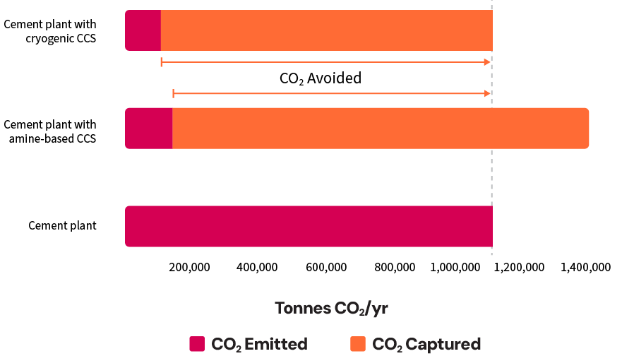
  • CO2 Avoided (Emissions Reduction): Both technologies significantly reduced CO2 emissions, but the cryogenic scenario achieved a slightly higher overall emissions reduction (i.e., 90% compared to 87% for the amine-based system). This difference is due to the amine system’s use of an auxiliary boiler, which introduced additional CO2 emissions. Although the flue gas from the auxiliary boiler is sent to the capture plant, only 90% of those emissions were captured, leaving 10% uncaptured and contributing to the lower overall emissions reduction.
  • CO2 Captured: The amine-based scenario captured approximately 30% more CO2 than the cryogenic scenario. This is because it also captured CO2 emissions from the auxiliary boiler used to generate steam for solvent regeneration, which is not required in the cryogenic scenario.


Utility Usage  


Key Insights:

  • Power Demand: Cryogenic capture required significantly more electricity, over 600 kWh per tonne of CO2 captured, which was approximately three times higher than the amine-based system (~200 kWh/t CO2). This makes electricity cost a critical factor when evaluating the economics of a cryogenic system.
  • Natural Gas Demand: Cryogenic capture does not use natural gas, while the amine-based system required 3.8 GJ per tonne of CO2. Cryogenic capture eliminates the dependency on natural gas prices and steam generation, giving it an advantage in regions with high natural gas prices or limited access to natural gas.
  • Total Energy Usage: When combining both electrical and thermal energy requirements, the cryogenic capture used approximately 67-85% of the total energy required by the amine-based system. The exact percentage depends on the efficiency factor used for converting electrical energy to thermal energy.
  • Energy Source Trade-Off: Cryogenic systems rely entirely on electricity, while amine systems use a mix of electricity and natural gas. Utility pricing and availability will influence the economics of each technology.
  • Emissions from Energy for Amine Regeneration: The auxiliary boiler used to supply steam for amine regeneration introduces additional emissions that are included in the amine-based capture plant design. Capturing these emissions requires a larger capture system and higher utility demands compared to a design that excludes them.


Impact of Utility Cost on Levelized Cost of CO2 Avoided    


Key Insights:

  • Cryogenic Independence from Natural Gas Prices: In both power price scenarios ($0.06/kWh and $0.12/kWh), the LCOA curve for cryogenic capture remained flat, showing no sensitivity to natural gas prices. This is because cryogenic systems do not rely on natural gas, making them advantageous in regions with volatile or high natural gas prices. 
  • Amine-Based System Sensitivity to Natural Gas Prices: For the amine-based system, the LCOA increased steadily with rising natural gas prices, reflecting its reliance on natural gas for steam generation.
  • Amine-Based and Cryogenic System Comparison: In both power price scenarios, the amine-based scenario appeared more economical when natural gas prices were low. However, as power prices increased (from $0.06/kWh to $0.12/kWh), the natural gas price threshold at which cryogenic capture becomes more cost-effective shifted higher. This means that at higher electricity costs, cryogenic systems only outperform amine systems when natural gas prices are significantly higher.


Economic Sensitivity for Cryogenic Carbon Capture  

To understand more details about the inputs and outputs of the economic model, click below:

Economic input overview

How to read a tornado chart


Key Insights:

  • Combined carbon price: When carbon tax and carbon credit pricing are correlated (i.e., both changed at the same time), they are the largest uncertainty in the project’s Net Present Value (NPV). Low combined carbon pricing (i.e., $0/tonne carbon credit price and $0/tonne carbon tax price) reduced NPV by almost 40%, and high combined carbon pricing (i.e., $85/tonne carbon credit price and $170/tonne carbon tax price) increased it over 50%, representing an uncertainty range greater than 90% of a project’s NPV.
  • CCUS-ITC: If the CCUS Investment Tax Credit (ITC) is cancelled or if a project is deemed ineligible to receive the tax credit, it decreased the project’s NPV by over 40%.
  • Capital costs: High capital costs (i.e., 50% higher than nominal) reduced the project’s NPV by nearly 30%, while low capital costs (i.e., 30% lower than nominal) increases NPV by approximately 18%.
  • Power price: Due to its energy-intensive refrigeration process, cryogenic capture is highly sensitive to electricity costs. High power prices, starting at $120/MWh, reduced the project’s NPV by approximately 26%. While lower power prices, starting at $60/MWh, increased NPV by approximately 9%.
  • Operating costs: High operating costs (i.e., 50% higher than nominal) reduced the project’s NPV by more than 16%, while low operating costs (i.e., 30% lower than nominal) increased NPV by approximately 10%.
  • ACCIP: If the Alberta Carbon Capture Incentive Program (ACCIP) is cancelled or if a project is deemed ineligible to receive the funding, it reduced the project’s NPV by 13%.
  • Natural gas price: Since there is no natural gas usage for this case, there is no impact of natural gas price on economics.


Conclusions

The main takeaways from this analysis are:

  • Cryogenic capture achieves slightly higher overall emissions reduction (90% vs. 87%) because amine systems require an auxiliary boiler for solvent regeneration, introducing additional emissions. These extra emissions increase the amount of CO2 that must be captured, about 30% more, resulting in a larger capture plant and higher utility requirements.
  • When accounting for both electrical and thermal energy requirements, cryogenic capture consumes approximately 67–85% of the total energy required by an amine-based system.
  • At higher electricity costs, cryogenic capture economics are more favorable than amine-based capture only when natural gas prices are significantly higher.
  • The NPV is most sensitive to combined carbon pricing. The ability to generate revenue through carbon credits and/or avoid paying carbon taxes is essential for carbon capture economics.
  • Cryogenic carbon capture economics are highly sensitive to power price but are unaffected by the cost of natural gas. This makes the technology particularly attractive in regions with low-cost power or where natural gas is expensive or not readily available.
  • Economic risks can be reduced through engineering studies to improve capital and operating cost certainty. Long-term agreements for carbon credit pricing, natural gas pricing, and electricity pricing can improve certainty in revenue streams and operating costs.